


 English (pdf)
 Article in xml format
 Article references
 Send this article by e-mail
 Cited by SciELO
  Similars in
SciELO
Similars in
SciELO 
 Permalink
Introduction
Temporary restoration is a crucial step for fixed, dental and implant supported prosthodontics, because it is the middle step between the diagnosis and subsequent treatment (1,2) helping with modeling soft tissues after bone or tissue grafts (3) and allowing the patient to evaluate the shade, shape, size, position and overall comfort of the proposed rehabilitation in function before cementation of definitive restorations (4,5,6) Recently, the development of CAD/CAM technologies for applications in Dentistry, introduced software design of temporary and definitive fixed restorations (7,8,9). The first approaches to digital design and manufacturing consisted mainly of subtractive milling of the planned restoration from a pre-polymerized or pre-sintered block of the restorative material (10,11,12,13). Despite the importance of the development, the main disadvantage associated with subtractive CAD/CAM methods is that much of the material is wasted as a result of the milling process (13,14,15).
Advances on CAD/CAM technologies for dental resins resulted in the development of additive manufacturing techniques, also known as 3D-printing, where the restorations are fabricated in incremental layers restricted to the contour of the desired shape, thus, the amount of discarded material is reduced (14,15). Among resin 3D-printing techniques, digital light processing devices offer a relatively fast processing, low cost and high resolution (16,17). This technique consist of a DLP projector in intimate contact with a resinfilled container. The projector emits light through an intermediary screen and the photoinitiators in the resin are activated (18) and polymerize the overlying resin in the desired shape and height to form a layer (15). The process is subsequently repeated until all the layers are printed, and the restoration is complete. Despite the convenience of this technological advance, and because the clinical application of new techniques advances at a faster rate than the research that validates them (19) there are still concerns related to the design and manufacturing processes such layer thickness (20) printing angulation (21,22) and the post-curing protocols (23-24). Other concerns, however, are related to the chemical and mechanical compatibility of 3D-printed resins with other restorative materials (25,26,27).
The mechanical performance of 3D-printed resins has been the subject of recent studies (28,29,30) that have focused mainly on the tensile (16) flexural (17,24,31,32,33) and compressive strength of these materials (34) and other properties such as microhardness (35,36,37) degree of conversion (31,38,39) color stability (31,40) and accuracy of the restorative resins (21,41,42,43). However, there is a lack of information related to the possibility to bond to 3D-printed resin indirect restorations (44,45). Adhesive cementation of 3D-printed resins would largely increase the clinical applications of these materials and make for an attractive treatment option in cases where long-term provisional restorations are required (3,46). Moreover, there are no clear guidelines on the best approach to prepare the surface of 3D-printed resins for bonding, either by chemical or mechanical treatments, although previous studies (47,48) have proposed the application of airborne particle abrasion (APA) (44,45,47,48,49) and chemical primers (50,51) as a mean to increase the bond strength to resin-based cements.
Thus, considering the importance of adequately retained interim fixed restorations, and the insufficient information about clinical protocols for adhesive cementation of 3D printed resins, the purpose of this study was to evaluate the effect of surface treatments on the microtensile bond strength (µTBS) of two resin cements to four digitally manufactured restorative resins, after 24 hours of water storage or thermocycling. The following null hypotheses were tested: 1. regardless of the type of cement or APA approach, there would not be diffe- rences on the µTBS of the evaluated 3D printing resins; 2. regardless of the type of cement, diffe- rent APA protocols would not produce changes on the µTBS of the different resin; 3. regardless of the material and APA treatment, there would not be differences between the evaluated cements; and 4. there would be differences on the µTBS before and after thermal cycling.
Material and methods
Analysis of the emission spectrum of the 3d-printer
Qualitative emission spectrum from the 3D-printer (Photon, Anycubic Technology Co., Shenzen, China) was obtained using a calibrated spectrophotometer (Flame S-VIS-NIR, Ocean Insight, Orlando, FL, USA) coupled to a 600 μm fiber optic with a cosine corrector (CC-3-UV-S, Ocean Insight, Orlando, FL, USA) with 6.35 mm diameter. A software (OceanView version 2.0.7, Ocean Insight, Orlando, FL) was used to record and export the emission data to a spreadsheet software (Excel 2016; Microsoft, Redmond, WA, USA). The cosine corrector was fixed perpendi- cular to the printer screen, and the printer was set to print a figure using the total emitting area of the screen. The emitted wavelength range was recorded 3 times and the mean value for each wavelength was calculated.
Tested materials and experimental design
Four different resins, indicated for fabrica- tion of temporary fixed restorations using CAD/ CAM technology were selected for this study. Three are designed for additive manufacturing in digital light processing (DLP) 3D-printers: Cosmos Temp 3D (COS, Yller, Pelotas, RS, Brazil); Smart Print Bio Temp (SMA, MM Tech, São Carlos, SP, Brazil) and Resilab 3D Temp (RLB, Wilcos, Petró- polis, RJ, Brazil). The fourth material is designed for subtractive manufacturing by milling processing (CAD/CAM): VitaCAD Temp (VIT, Vita Zahnfabrik, Bad Säckingen, Germany). Specifications about the composition, lot number, and shade of the tested products are presented in Table 1.
The printed samples were designed using a 3D processing software (MatterControl v.2.20.1.10422, MatterHackers, CA, USA) and exported to a printer slicer software (Chitubox 64, Chitu Systems, GD, China) using the manufacturer indicated parameters for exposure and off time. Layer height was set to 50 µm at 0° angulation for all the materials and experiments (33). Specimens for the 3D-printed materials were manufactured using the same root STL files to ensure equal specimen characteristics. Then, specimens were washed with isopropyl alcohol under agitation for 10 minutes and post cured with violet light (Wash and Cure 2.0, Anycubic Technology Co., Shenzen, China). For the milled resin, the samples were obtained from a CAD/CAM block (CTM-40) using a low-speed diamond- wafering blade (Isomet 1000 Precision Saw; Buehler Co., Lake Bluff, IL, USA) at 200 rpm with 150 g load.
Table 1 Classification, brand names, lot number, compositions, and shade of the evaluated materials.
| Classification | Brand name and Lot number | Composition | Shade |
|---|---|---|---|
| 3D Printed resin | Cosmos Temp 3D (COS) Lot 00008288 | Methacrylate oligomers, diphenyl-2,4,6-trimethyl benzoyl phosphine oxide (TPO), titanium dioxide, carbon black. | A1 |
| - | Smart Print Bio Temp (SMA) Lot PTPB1010/20 | Methacrylic ester monomers, stabilizer, fillers, pigments, photoinitiators, accelerators. | B1 |
| - | Resilab 3D Temp (RES) Lot 1417 | Information not provided by the manufacturer. | A1 |
| Milled resin | VitaCAD Temp (VIT) Lot 48000 | Poly(methyl methacrylate), silicon dioxide, pigments. | 1 M2T |
| Resin Cement | Panavia V5 (PAN) Lot 450053 | Paste A: Bis-GMA, TEGDMA, hydrophobic aromatic dimethacrylate, hydro- philic aliphatic dimethacrylate, initiators, accelerators, silanated barium glass, Silanated fluoroalminosilicate glass. Paste B: Colloidal silica, Bis-GMA, Hydrophobic aromatic dimethacrylate, hydrophilic aliphatic dimethacrylate, silanated barium glass, Silanated aluminum oxide, accelerators, camphorquinone, pigments. | A1 |
| - | RelyX Ultimate (REX) Lot 7405361 | Base Paste: Methacrylate monomers, radiopaque silanated fillers, initiator components, stabilizers, rheological additives. Catalyst Paste: Methacrylate monomers, Radiopaque alkaline fillers, initia- tor components, stabilizers, pigments, rheological additives, fluorescence dye, Dual cure activator for Universal Adhesive. | A1 |
Morhology of the surface of the resin
For the 3D-printed materials, three plates (5 mm length x 8 mm width x 1 mm height) were printed for each resin. For the milled resin, plates of the same dimensions were separated from a resin block. After all plates were prepared, one half of the plate was covered with isolating tape (Temflex 1700, 3M Electrical Markets Division, Austin, TX, USA) and the other half was treated by airborne particle abrasion (APA) using a dental air abrasion unit (Microetcher II, Danville Engineering, San Ramon, CA, USA) with alumina particles (50 μm, Bio-Art, São Carlos, SP, Brazil) during 10s at
0.2 MPa (47,51). The samples were then ultrasonicated for 3 min in distilled water. The other half of the plate was left untreated (No air abrasion, NAA). Then, the resin plates were stored in a desiccator with silica gel for 24 hours before sputter coating with gold (Desk ll, Denton Vacuum Inc., NJ, EUA) and examined using an SEM (JSM IT 300; Jeol, Tokyo, Japan) at 400X magnification.
Microtensile bond strength
For each evaluated resin, 64 cubic-shaped samples (5x5x5 mm) were fabricated using the previously described equipment and procedures (Figure 1.A). For each material, the blocks were randomly divided into four groups (16 cubes per group, 1 pair of blocks per bonded specimen) accor- ding to the surface treatments, APA or NAA and two resin cements (Panavia V5, PAN, Kuraray, and Rely X Ultimate, REX, 3M Oral Care). For the 3D-printed blocks, the face of the cubes where the fabrication supports were attached was painted using a water-resistant varnish (Colorama, CEIL Ind. Ltda., São Paulo, SP), Brazil, and for the milled resin, one of the faces was randomly selected for painting. The side of the block opposing the painted face was treated with APA or not (NAA) (Figure 1.B). Regardless the surface treatments (APA or NAA), the adhesive (for REX) or the primer (for PAN) were applied to provisional resins, followed by their respective resin cement (52).
A pair of blocks that received the same surface treatment were used for bonding. To ensure adequate alignment of the resin blocks during cementation, one block was inserted into a heavy-body silicone matrix with drainage holes on each side of the silicone matrix to allow the exit of any excess cement. The matrix fitted the block snuggly, while leaving the bonding surface exposed. The resin cements were mixed, and a thin layer of cement was applied on the previously treated surfaces of the blocks (Figure 1.C). A second block was placed into the silicone matrix, with the bonding faces of each block facing each other. After seating the block in position, a 5 N load was applied for 5 minutes before removing any excess cement (47). Then, the cemented specimens were removed from the silicone matrix and complementary 20s light curing cycles (Valo, Ultradent Products Inc., South Jordan, UT, 1060 mW/cm² emittance) were applied on each side of the blocks. Excess of resin cement was removed from the cemented blocks, and they were stored in distilled water for 24 h at 37°C (Figure 1.D) and sectioned into approximately 1 × 1 mm specimens or sticks (cross sectional area of 1 mm2) using a low-speed diamond-wafering blade (Isomet 1000 Precision Saw; Buehler Co., Lake Bluff, IL, USA) at 200 rpm with 150 g load (Figure 1.D).
For each block, approximately 16 sticks were obtained and divided in two groups, one group was tested immediately, and the other half was stored in water for 7 days before the application of thermal cycling (OMC 300 TSX, Odeme Dental Research, Luzema, SC, Brazil) for 5,000 cycles (5°C to 55°C, 30 s dwell time, 5 seconds transfer time) before µTBS testing (Figure 1.E) (54,55). For the µTBS test, each stick was fixed to a custom microtensile testing device using cyanoacrylate glue (Super Bonder Power Flex, Loctite, São Paulo, SP Brazil) with an accelerator (Zap Zip Kicker, Pacer Technology, Ontario, CA, USA) (Figure 1.E) (25,56). The device was placed in a Universal testing machine (EZ-test-500N, Shimadzu Co., Kyoto, Japan), and a tensile load (1 mm/min) was applied until failure (Figure 1.G) (55). The sides of the sticks were measured with a digital caliper (Mitutoyo Corp., Kawasaki, Japan) to calculate the bonded area and for posterior calculation of the µTBS strength (MPa) from the load (N) at failure. The mean µTBS value of all the sticks obtained from the same cemented block was considered as the µTBS of the specimen. All measurements were performed by a trained operator, blinded to the group being tested.
Failure pattern analysis
For the failure pattern analysis, the fractured specimens were dried, sputter-coated with gold (Desk ll, Denton Vacuum Inc., NJ, EUA) and examined by SEM (JSM IT300; Jeol, Tokyo, Japan) at 250X magnification. The failure patterns were classified as: 1. Cohesive fracture within the resin cement, 2. Adhesive failure between the cement and the provisional restorative resin, 3. Mixed failure, and 4. Cohesive fracture within the provisional resin (25).
Statistical analysis
For the µTBS analysis, pre-test failures were treated as left-censored data, and a value corresponding to the mean between 0 and the lowest measured value in the group was assigned to the stick (54). The mean value of all the evaluated sticks from each block was considered as the µTBS of the specimen and used for statistical analysis. Data for µTBS was analyzed by Generalized linear model (between-subject factors: ''Provisional Resin”*”Air-abrasion''*”Resin Cement”; between-subject factor: ''Time”), and the Bonferroni method was used to correct for multiple testing (P<0.05). For the failure pattern analy- sis, the incidence rate of each fracture type was calculated as a percentage for each group. The statistical analysis was performed using SAS 9.3 (SAS Institute, Cary, NC, USA).
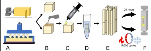
Figure 1 Schematic representation of the sample preparation for the µTBS test. A. 5 x 5 x 5 mm side, resin blocks where either 3D-printed or cut from a prepolymerized block; B. The obtained cubes were divided into groups and the bonding surface was treated by airborne particle abrasion or left untreated according to the corresponding treatment; C. The corresponding primer and cement were applied on the bonding surface, and a second block was placed over the cement layer; D. The obtained specimens were stored in water for 24 hours prior to TBS stick preparation; E. 1 x 1 mm side, µTBS stick specimens were obtained from the cemented resin blocks and divided in two different groups according to the time of evaluation; and F. The specimens were fixed in a testing jig using cyanoacrylate glue and tested under tensile load.
Results
Analysis of the emission spectrum of the 3d-printer
Information about the emission spectrum the used DLP 3D-printer is presented in Figure 2. The emission of the printer ranges from 395 to 425 nm with a maximal peak of 408 nm. Hence, the emission spectrum corresponds mostly to violet light.
Surface morphology
Representative images of the APA and NAA surface for each resin are presented in Figure 3. In general, the microphotograph images show evident differences between the NAA and APA regions for all resins. The APA areas of all materials present a rough, irregular morphology, characterized by the presence of groves and edges, although for VIT, the created defects appear shallower compared to the 3D printed resins, although there is a perceptible roughening of the surface. On the other hand, the NAA surfaces appear smooth and undamaged, both for the 3D-printed resins and the milled acrylic resin.
Microtensile bond strength
Mean µTBS values are reported in Table 2. The GLM analysis indicated that factors resin (P<0.001), air abrasion (P<0.001) and time (P<0.001) significantly influenced the results. However, the quadruple interaction between factors resin*cement*air abrasion*time was significant (P<0.001). In general, 3D printed resins exhibited significantly higher bond strength than VIT, regardless of the cement, the air abrasion treatment, and the evaluation time. For the 3D-printed resins, differences between resin cements were mostly material dependent. At the 24-hour evaluation REX produced a higher µTBS for COS for NAA, while PAN was significantly higher for SMA associated with APA. After thermocycling, REX had significantly higher µTBS values for COS associated with APA, and for RSL on NAA. For the other group comparisons there were no significant differences. The application of APA did not result in a clear trend of higher µTBS for the evaluated 3D-printed resins.
Regarding VIT, the µTBS values were significantly higher at the 24-hour evaluation when REX was used for the APA treated group, and after thermocycling regardless of the APA treatment. It must be considered that VIT presented the highest amount of pre-test failures for all the evaluated materials, making impossible the measurement of the µTBS on the NAA group after thermal cycling when PAN was used. As for the effect of APA, the application of APA produced significantly higher µTBS values for VIT after 24 hours when REX was used, and for both resin cements after thermal cycling.
Failure pattern
The rate of incidence of each failure pattern, according to the material, resin cement, air abrasion and evaluation time are presented in Figure 4. Also, representative SEM images of each failure type are presented in Figure 5. Regardless of the resin cement and APA treatment, a higher rate of Type 2 failures (between resin and cement) was observed at both evaluation times. Regarding the APA groups, for PAN at the 24-hours evaluation, the rate of Type 4 failures (cohesive within provisional material) was higher than on the NAA groups. For VIT on the other hand, the most frequent type of failure where Type 2, and there were no Type 4 failures on any evaluated condition. Also, for all groups, the rate of Type 2 failures increased after thermal cycling.
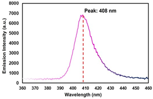
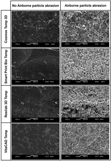
Figure 3 Representative SEM images (x250 magnification) of the restorative resins reveal different textures between the air abraded and the non-air abraded surfaces. The air abraded resin surfaces present an irregular morphology, characterized by the presence of groves and edges, while the non-air abraded surfaces exhibit a smooth texture.
Table 2 Mean (95% C.I.) microtensile bond strength of evaluated resins, according to evaluation time, resin cement (Panavia V5 or RelyX Ultimate), and airborne particle abrasion treatment, in MPa.
| - | - | Cement | - | - | - |
|---|---|---|---|---|---|
| Measurement time | Material | Panavia V5 | - | RelyX Universal | - |
| - | - | APA | NAA | APA | NAA |
| - | - | 27.5 (24.4 - 30.6) aA (0) | 21.0 (18.5 - 23.6) bB (1) | 27.3 (24.2 - 30.4) aA (0) | 29.5 (26.2 - 32.8) aA (1) |
| - | SMA | 28.2 (25.0 - 31.4) aA (0) | 27.1 (24.0 - 30.1) aA (1) | 20.0 (17.6 - 22.5) bB (0) | 29.1 (25.8 - 32.3) aA (2) |
| - | RES | 25.4 (22.5 - 28.3) aA (0) | 23.9 (21.1 - 26.7) abA (0) | 27.3 (24.0 - 31.1) aA (0) | 27.2 (24.1 - 30.3) aA (0) |
| - | VIT | 8.6 (7.3 - 9.9) bB (1) | 8.5 (7.2 - 9.8) cA (2) | 14.6 (12.6 - 16.5) cA (1) | 3.8 (3.1 - 4.5) bB (3) |
| 5,000 | COS | 21.4 (18.8 - 24.0) bB* (1) | 22.4 (19.7 - 25.0) aA (1) | 31.0 (26.7 - 33.3) aA (1) | 25.9 (22.9 - 28.9) aA (0) |
| Thermal cycles | SMA | 26.9 (23.8 - 29.9) aA (0) | 25.2 (22.3 - 28.1) aA (0) | 22.5 (19.8 - 25.1) bA (1) | 26.9 (23.8 - 29.9) aA (0) |
| - | RES | 30.9 (27.5 - 34.3) aA* (1) | 22.2 (19.6 - 24.9) aB (0) | 31.2 (27.8 - 34.7) aA (1) | 27.4 (24.3 - 30.5) aA (0) |
| - | VIT | 7.1 (6.0 - 8.2) cB (3) | 0.0 (0.0 - 0.0) bB* (8) | 15.6 (13.5 - 17.6) cA (2) | 1.8 (1.4 - 2.2) bA* (5) |
Lower case letters compare restorative resins within the same treatment, resin cement and time. Upper case letters compare different resin cement within the same restorative resin, treatment and time. Connective bars indicate significant different between treatments within the same resin composite, resin cement and time. (*) Differ from 24h within the same resin composite, resin cement and treatment.
Values between ( ) indicate the number of pre-test failures for the group.
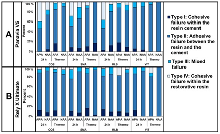
Figure 4 Distribution of failure modes after 24-h and 5,000 cycles of thermal aging, according to airborne particle abrasion treatment A- for Panvia V5, and B- for Rely X Ultimate.
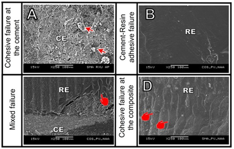
Figure 5 Representative SEM images of each failure type. A. Type 1: Cohesive failure at the resin cement. The filler particles can be observed, and the surface of the restorative resin is completely covered by remaining cement (Air abraded, Smart Print Bio Temp and Rely X Ultimate, after 24 hours); B. Type 2: Adhesive failure between the resin cement and the restorative resin. The image shows the smooth surface of the cement over the restorative resin (Non-abraded, Cosmos 3D Temp and Panavia V5 after thermal cycling) C. Type 3: Mixed failure. The image shows the fractured cement layer, and the exposed surface of the restorative resin. Also, the pointer indicates the presence of areas where separation of the layers of the restorative resin occurred. (Non-abraded, Cosmos 3D Temp and Panavia V5after 24 hours); D. Type 4: Cohesive failure within restorative resin. The presence of fracture lines within the the layers of the restorative resin are visible (Non-abraded, Smart Print Bio Temp and Panavia V5 after 24 h).
Discussion
The results of this study showed that 3D printed resins are a clinically adequate material for long-term, temporary fixed restorations on esthetic regions, where adhesive cementation is required to obtain adequate retention and adaptation. Based on the findings of this study, the first null hypothesis was rejected because there were significant differences on the µTBS of the evaluated resins. In general, the 3D printed resins obtained a higher µTBS than the milled resin VIT, regardless of the APA procedure, resin cement used, and evaluation time. Also, despite the a few statistically significant differences between the 3D-printed resins, those differences are unlikely to be clinically relevant, because the evaluated materials exhibited a µTBS of approximately 20 MPa or higher regardless, of the type of resin cement, surface treatment and evaluation time, comparable to the values reported previously for indirect resin composites (49).
In this study, differences on the polymerization of the provisional restorative material are unlikely to affect the evaluated resins, because despite the limited penetrability of violet light (18) each layer had a controlled thickness of only 50 µm, which was keep identical for all the materials. Also, the manufacturer of COS reports that it contains the type I photoinitiator known as Lucirin-TPO, which has an adequate absorption for light in the wavelength range of the selected printer (18,24). It would be expected that the other 3D-printer resins present similar photoinitiators optimized for the emission spectrum of 3D-printers (18).
On the other hand, comparison of the 3D-printed resins with the pre-polymerized milled material, showed that all the 3D-printed resins had a higher µTBS. This result could be explained by a joint copolymerization of the unreacted monomers on the 3D-printed resins with the monomers on the resin cements (44) that does not occur on VIT. The evaluated 3D-printed resins are methacrylate-based materials and therefore, a high affinity between the unreacted monomers on the 3D-printed resins and those on the resin cement could be expected. On the other hand, VIT is a pre-polymerized block of high molecular weight, densely crosslinked acrylate polymers (12) manufactured under high temperature and pressure conditions (9). The block of VIT presents a very high degree of conversion and absence of photoinitiators, thus exhibiting little reactivity of residual monomers to copolymerize with the resin cement (7). This could also explain why a previous study reported that debonding is a weak point of temporary restorations made from VIT (10). This result is in line with previous studies that demonstrated bonding of indirect resin restorations strongly depends on the micro-retentions created by the APA treatment (10,47,51).
The second null hypothesis was accepted because for all the evaluated material, the application of APA influenced the µTBS under some of the evaluated conditions. Traditional surface treatment of indirect resin restorations indicates using APA with alumina abrasive particles to create micro-mechanical retentions (47). Hence, this study intended to determine if this principle also applies to 3D-printed restorations, or if the use of resin cements combined with primers containing functional monomers could result in adequate bond strength between the restorative resin and the resin cement. For the 3D-printed resins, when PAN was used, APA only produced a significant increase on the µTBS of COS at the 24-hour evaluation and for RSL after thermalcycling. For the other 3D-printed resins, there were no differences regardless of the evaluation time. On the other hand, when REX was used, SMA presented a higher µTBS on the NAA groups at both evaluation times.
For the other 3D-printed resins, there were no significant differences between the APA and the NAA protocols. These results corroborated a previous study, where the application of mechanical treatment on the surface of 3D-printed resins did not increase the shear bond strength of acrylic and bis-acrylic resins (44). For VIT, the application of APA significantly improved the µTBS to both resin cements, especially after thermal aging. As mentioned before, bonding to pre-polymerized, milled resins heavily depends on the creation of intricate mechanical interlocking between the restorative material and the cementing agent (51). However, the findings of this study do not support the application of APA as a standard surface conditioning of 3D-printed resins for adhesive cementation. Although the analysis of the SEM micrographs demonstrated notorious differences between the APA and NAA surfaces of all the evaluated resins, the roughening of the surface produced by APA did not translate into a remarkably higher µTBS on the 3D-printed resins. Also, it is important to highlight that for the 3D-printed resins, there was a higher rate of type 4 fractures (cohesive fracture within the provisional resin) on the APA treated samples, compared to the NAA groups. As observed in the SEM images, these failures were characterized by the separation of the printed layers within the sample, thus suggesting that the tensile strength of the material was surpassed.
For 3D-printed resins, several factors such as the layer thickness (15,32) specimen angulation (22,28,30,34) and the washing (29,39) and post curing (23,24,28,31,38) protocols may weaken the cohesivity of the layers of the specimen and affect the truthfulness of the µTBS evaluation. Because the samples in this study were printed at 0° angulation, the layers were perpendicular to the load (34). This could have increased the rate of type 4 failures, because of the delamination between the printed layers, that at 0° angulation have the smallest possible contact area. Hence, printing at a different angulation might be recommendable for restorations that will be subjected to tensile load because the applied forces will be directed in a more favorable direction (16,33) and there will be a greater contact area between the printed layers (33). Further research addressing the influence of the build angle on the ultimate tensile strength of 3D-printed resins is required to confirm this supposition. Nonetheless, the obtained results confirm that there is not a clear benefit on the application of APA for the adhesive cementation of temporary 3D-printed restorations, because it could produce superficial damage to the 3D-printed restoration, without significantly improving its bond strength.
The third research hypothesis was rejected because significant differences were identified between the resin cements. The observed differences; however, are inconclusive. On the NAA groups, REX presented a higher µTBS than PAN for COS at the 24-hours evaluation. For the APA treated groups, REX produced a higher µTBS for RSL and VIT after thermal cycling. The more stable union between VIT and REX compared to PAN, may be produced by the chemical compatibility between the silane contained on the universal bonding agent and the silicon particles contained on the resin block (50). Also, for the 3D-printed resins, co-polymerization with the adhesive and the resin cement may explain the maintained µTBS values. On the other hand, the absence of dental tissues led to a modification on the application mode for PAN, by applying Tooth Primer on the surface of one of the resin blocks. Although the Tooth Primer is intended to be placed on dental tissues, this primer also contains an accelerator for the self- curing reaction of PAN, and for that reason it was applied to ensure that the resin cement would be evaluated under the most adequate polymerization conditions (53). However, the acidic pH of the primer is not neutralized on the absence of ions from the tooth and may affect the long term performance of the resin cement, by inhibiting the catalytic components in charge of the post-cure reaction on the resin cement (25,26,27).
The fourth and final hypothesis was upheld for the 3D-printed resins, and rejected for the milled material, because thermal cycling produced differences on the µTBS of VIT. The results showed that for the 3D-printed resins, thermal cycling did not result in significant differences on the µTBS when REX was used. For VIT, the µTBS decreased on the NAA groups with both evaluated resin cements. It has been proposed that thermal cycling is a useful tool to predict the mode of failure of a material. On that regard, the findings of this study showed that thermal cycling produced an increase on the rate of Type 2 failures, on all the evaluated materials, which was confirmed by the increased number of pre-test failures. Also, despite the application of a statistical compensation, the higher number of pre-test failures may have influenced the µTBS results after thermal cycling, because a reduced number of sticks was evaluated compared to the 24-hour evaluation. Considering that the specimens with the weaker µTBS are more prone to failure, those exhibiting a higher µTBS may have survived the thermal cycling process and artificially overestimated the bond strength of the resin cements to the provisional restorative material.
It must be considered that even though a long-term evaluation of the µTBS of provisional restorative materials may not seem as relevant, the obtained results can be used to estimate the predictability of long term temporary fixed restorations. Although clinically it would be uncommon to bond temporary restorations, there are clinical scenarios that require long-term, fixed temporization, such as changes on the vertical dimensión (10) unclear prognosis for teeth before a definitive complex rehabilitation (10) and bone and tissue regeneration before implant placement (3). Also, the evaluation of the µTBS of resin cements to a recently developed kind of 3D printed, temporary restorative materials is important to provide validated information and avoid unnecessary steps on the cementation procedure.
Conclusions
Based on the findings of this study, resin cements offered a clinically acceptable bond strength to 3D-printed resins that is also resistant to thermal aging for most APA and NAA, while the milled acrylic resins present lower bond strength values. Also, specific surface treatment procedures are required for 3D-printed and milled resins, because of differences in the material manufacturing process. Hence, a combination of APA and adhesive/primer is advised to obtain a durable bonding of temporary, milled restorations. On the other hand, airborne particle abrasion does not result in a clinically relevant benefit for the cemen- tation of 3D-printed, fixed provisional restorations.
Funding
This study was financed in part by the Coordenação de Aperfeiçoamento de Pessoal de Nível Superior - Brasil (CAPES) - Finance Code 001 and the International Affairs Bureau of the University of Costa Rica (#OAICE-047-2017).
Author contribution statement
Funding: J.S.M. and M.G.
Design: J.S.M., M.S.N. and M.G.
Data acquisition: J.S.M. and B.C.R.
Analysis: J.S.M.
Interpretation and drafted the manuscript: J.S.M., and B.C.R.
Interpretation and critically revised the manuscript: M.S.N, C.B.A. and M.G.
Statistical analysis: C.B.A.
All authors gave final approval and agreed to be accountable for all aspects of the work.

