


 Spanish (pdf)
 Article in xml format
 Article references
 Send this article by e-mail
 Cited by SciELO
  Similars in
SciELO
Similars in
SciELO 
 Permalink
INTRODUCTION
Adhesion in dentistry facilitates the use of conservative and minimally invasive procedures, avoiding the need for excessive preparation of natural teeth when performing a dental restoration.
In this sense, occlusal veneers are a conservative alternative for the treatment of teeth with moderate or severe occlusal wear (1). The clinical procedure is used to restore or increase the oclusal vertical dimensions of a permanent natural dentition with moderate or severe wear (1,2).
Various materials have been studied in relation to the making of occlusal veneers, including ceramics, hybrid materials and composite resin, among others (3-7). Composite resin (CR) is a material with adequate resistance to wear, providing good absorption of occlusal forces and not generating wear on the opposing tooth (8). The first micro-filled CRs had a 40% filling volume; later the nano-filled CRs appeared with a 60% filling volume, thus improving their mechanical properties; for example, indirect CR restorations currently have a flexural strength range of 120 to 160 MPa (2). On the other hand, monolithic ceramic restorations perform adequately in posterior teeth (9,10). Lithium disilicate (LD) is a ceramic with excellent physical and mechanical properties (11), and multiple publications report its effectiveness in the preparation of occlusal veneers (1,9,12,13).
Furthermore, an in vitro study demonstrated a better resistance to fracture, compared to feldspathic ceramic in occlusal monolithic restorations (14). Likewise, others researches supports the strength of LD occlusal veneers with a thickness of less than 1mm (12,15,16). Medium-term success has also been reported in the clinical performance of ultra-thin occlusal veneers of 0.4mm to 0.6mm thickness (17).
There is a protocol for the preparation of indirect posterior restorations that mentions a butt join, bevel, or shoulder finishing line (18), although some authors have shown preparations where only the occlusal surfaces were abraded, following the inclination of the internal slopes of the cusps, and circumscribed to the occlusal table of molars and premolars, without any bevel (1,3,4,13,19,20). Meanwhile, other authors suggested beveling the cusps and extending the finishing line outside of the occlusal table (6,12,21,22). Furthermore, Yazigi et al. (23) presented their preparations for occlusal veneers in premolars, beveling only the support cusp and leaving the guide cusp without any bevel.
Finish lines for indirect ceramic restorations have been presented with chamfer and shoulder preparations (12,15,19), because they would allow for better resistance to fracture (24). However, recent studies have reported good performance of the feather-edge finish line preparation in monolithic disilicate crowns (25,26). Nowadays, ceramic laminated veneers have been used on non-prepared anterior teeth with good results in terms of marginal adaptation and intimate contact after years of follow-up (27).
Despite the fact that, the literature shows many forms of preparation for occlusal veneers in worn posterior teeth (15,19,28,29), no information was found on how the type of finish line influences the level of stress accumulated on the occlusal veneer. Therefore, the aim of the present study is to evaluate the stress values in LD and CR occlusal veneers with and without a beveled finish line, when receiving vertical forces to the center of the tabletop and tangential forces close to the finish line.
MATERIALS AND METHODS
After approval by the Institutional Ethics and Research Committee of Científica del Sur University with registration number 421-2019-POS8, based on the background, the study was carried out using the three-dimensional analysis method of finite elements (29).
SAMPLE PREPARATION
An extracted human lower third molar was used, with the occlusal surface preserved. After washing and immersing the tooth in a solution of hypochlorite and water in a ratio of 1 to 10, it was immersed in 2% glutaraldehyde solution for adequate disinfection. The tooth was then fixed on a plaster base in order to make an impression with addition silicone (Panasil® Putty Soft; kettenbach, Eschenburg, Germany) to register the intact occlusal surface.
PREPARATION AND SCANNING OF THE NON-BEVELED OCCLUSAL VENEER
The first preparation was carried out on the internal slopes of the occlusal surface, creating guide grooves with a blue-ribbon diamond bur No.837L.010 (Jota; Jota AG, Rüti, Switzerland), uniformly grinding 1mm deep, and preserving the approximate cusp inclination of 20°. Then, using a red ribbon diamond bur No.837L.010, the preparation was standardized. Finally, the prepared surface was polished with abrasive discs (Sof-lexTM; 3M ESPE, St. Paul, USA), preserving the gradient of the internal slopes.
The tooth preparation was scanned in a dental scanner (3Shape R2000; 3Shape, Copenhagen, Denmark) using 3Shape Dental System software, to design the 1mm thick occlusal veneer, for which the occlusal anatomy of a lower first molar preset by the program was used. Then, the data from the molar scan and the computer-aided design (CAD) of the occlusal veneer were exported in STL (Standard Triangle Language) format.
PREPARATION AND SCANNING OF THE BEVELED OCCLUSAL VENEER
The initial molar was beveled using a diamond bur No.893F.023 (Jota; Jota AG, Rüti, Switzerland), keeping the bur in a horizontal position so that the bevel of the margins followed the contour of the shape of the bur, translating the finishing line towards the external buccal and lingual slopes. The tooth preparation was polished with abrasive discs (Sof-lexTM; 3M ESPE, St. Paul, USA).
The molar with the new finish line was scanned using a scanner (3Shape R2000; 3Shape, Copenhagen, Denmark) that uses 3Shape Dental System software, and then the 1mm thick oclusal veneer with the new finish line was designed, covering the buccal and lingual cusps with a long bevel. Both the scan and the designed occlusal veneer were archived in STL format for further processing.
CONVERSION TO A SOLID BREP (BOUNDARY REPRESENTATION)
The 3Shape Dental System software generates exportable data in STL format. Using CAD/CAM software (Fusion 360; Autodesk, California, USA), the occlusal veneers and their respective molars, each scanned separately, were homogenized and the meshes were closed. The virtual veneers were assembled with their respective molars (Figure 1).
Subsequently, using the same CAD/CAM software, these pieces were converted to BREP solids, which were characterized by being formed by triangular polygons and exported in a neutral IGES (Initial Graphics Exchange Specification) format that allows the digital exchange of information between information systems.
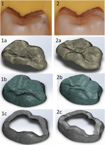
Figure 1 Third molar preparation for 1mm occlusal veneer and virtual model design. 1: non-beveled preparation in molar piece, 1a: non-beveled virtual occlusal veneer, 1b: virtual dentin, 1c: virtual non-beveled enamel. 2: beveled preparation in molar piece, 2a: beveled virtual occlusal veneer, 2b: virtual dentin, 2c: virtual beveled enamel.
DESIGN OF COMPONENTS AND PREPARATION FOR ANALYSIS
The final file was imported into the finite element analysis software (SolidWorks 2020; Dassault Systèmes-SolidWorks Corporation, Massachusetts, USA), and the assembled models were improved to obtain the following components: the prepared molar piece (composed of enamel and dentin) and the occlusal veneer, generating the volumetric meshes (total number of elements: 148101 and number of nodes: 229388) where the properties of each material were attributed (Table 1).
Table 1 Material properties.
| Material | Elastic modulus (GPa) | Poison’s ratio |
| Enamel* | 84.1 | 0.3 |
| Dentin* | 18.6 | 0.3 |
| IPS e.max Lithium disilicate* | 95 | 0.23 |
| Filtek Z350 Composite resin** | 11.3 | 0.3 |
*Extracted from: Modeling of ultrathin occlusal veneers.21
**Extracted from material technical sheet
The elements for analysis were established after making a tooth coronal section, above the pulp chamber. Fixing points were set at sections to focus the analysis on the occlusal veneer and the adjacent teeth structures, and then the external loads were configured. The groups were divided in order to analyze the occlusal veneers without bevel in groups 1 and 2, and with bevel in groups 3 and 4, and then, the groups were subdivided into lithium disilicate and composite resin (Table 2). The first analyses were performed using a vertical force of 400 N at the central fossa, simulating tripodic contact with the resultant vector parallel to the axis of the tooth. The other analyses were performed by applying a tangential force of 900 N, which exerts a single force on the top of the mesio-buccal cusp. Both forces were applied over occlusal veneers with beveled and non-beveled finish lines, over both dental materials (LD and CR).
Table 2 Study groups designation
| Lithium disilicate | Composite resin | ||
| Non-beveled | Group 1 (400 N) | 1A | 1B |
| Beveled | Group 2 (900 N) | 2A | 2B |
| Beveled | Group 3 (400 N) | 3A | 3B |
| Beveled | Group 4 (900 N) | 4A | 4B |
Group 1: Non-beveled occlusal veneers with 400 N vertical force.
Group 2: Non-beveled occlusal veneers with 900 N tangential force.
Group 3: Beveled occlusal veneers with 400 N vertical force.
Group 4: Beveled occlusal veneers with 900 N tangential force.
RESULTS
The results of the von Misses stress analysis, carried out by applying 400N on the central fossa, revealed that the non-beveled occlusal veneers showed higher maximum stress values (group 1A: 783 MPa and 1B: 736.5 MPa) than the beveled veneers (groups 3A: 685.7 MPa and 3B: 675.8 MPa). Conversely, when applying 900 N in a tangential direction on the mesio-buccal cusp of the occlusal veneer, the beveled veneers showed higher maximum stress values (groups 4A: 4297 MPa and 4B: 4133 MPa) than the non-beveled veneers (group 2A: 2581.1 MPa and 2B: 3519.1 MPa).
Similarly, when evaluating the underlying dental structure after applying 400N, the virtual enamel under the non-beveled occlusal veneers did not show any tension (groups 1A: 0 MPa and group 1B: 0 MPa), compared to the enamel underlying the beveled occlusal veneers, which showed high maximum stress values (group 3A: 23,204.6 MPa and group 3B: 8,514.0 MPa). The virtual dentin under the beveled veneers showed higher maximum stress values (groups 3A: 9,324.4 MPa and 3B: 5,375.9 MPa) than the dentin under the non-beveled veneers (group 1A: 27.8 MPa and 1B: 55.5 MPa).
In the stress analysis carried out by applying 900 N in a tangential direction, the dental enamel under the non-beveled occlusal veneers did not show any stress (groups 2A: 0 MPa and group 2B: 0 MPa) compared to the enamel under the beveled occlusal veneers (group 4A: 27,129.8 MPa and group 4B: 24,784.2 MPa). Using the same tangential force, the dentin under the beveled veneres showed higher maximum stress values (groups 4A: 26,777.6 MPa and 4B: 7,559.8 MPa) tan the dentin under the non-beveled veneers (group 2A: 1,024.6 MPa and 2B: 3,744.3 MPa) (Table 3, Figure 2 and Figure 3).
Table 3 Results, Maximum stress in MPa
| Finish line | Occlusal veneer von mises (MPa) | Dentin von mises (MPa) | Enamel von mises (MPa) | |
| Non-Beveled | Group 1A | 783 | 27.8 | 0 |
| Group 1B | 736.5 | 55.5 | 0 | |
| Group 2A | 3,581.1 | 1,024.6 | 0 | |
| Group 2B | 3,519.1 | 3,744.3 | 0 | |
| Beveled | Group 3A | 685.7 | 9,324.4 | 23,204.6 |
| Group 3B | 675.8 | 5,375.9 | 8,514.0 | |
| Group 4A | 4,297.0 | 26,777.6 | 27,129.8 | |
| Group 4B | 4,133.2 | 7,559.8 | 24,784.2 |
Groups 1 & 3: 400 N vertical force; Groups 2 & 4: 900 N tangential force; A: Lithium disilicate; B: Composite resin


DISCUSSION
The aim of this study was to evaluate stress distribution using the finite element analysis method, in one-millimeter-thick LD and CR oclusal veneers, with two different finish lines, applying a vertical force of 400 N and a tangential force of 900 N. According to the results, the beveled oclusal veneers displayed better stress distribution than to the non-beveled occlusal veneers when applying the tangential force of 900 N. However, the same did not occur when applying the vertical force of 400 N.
Stress analysis using the finite element method involves simulated forces that are applied in the same way to all samples and enables the visualization of the stresses produced within each analyzed structure. Using the color scale from blue to red, it is possible to see the degree of tension in both the occlusal veneers and the underlying structures.
The virtual models were obtained by scanning an extracted molar prepared for the occlusal veneer, with the aim of building a virtual model close to the real thing. Only a segment of the crown was used, with an axial cut being made above the empty space of the pulp cavity. This study omitted the resin cement and adhesive layer because is too thin. This layer was also omitted in other studies, which mention that despite the elastic modulus of the cement and the adhesive layer seeming to work mechanically as a stress absorber, this is an extremely thin layer to be included in the study (approximately 100μm thick). Furthermore, the results were not affected by the omission in those other studies that followed the same experimental methodology (19).
Bite force depends on various factors, such as age, gender, joint or muscular conditions and even the technique used to record it (30). Some authors affirm that the average bite force excedes 300 N (31,32). Waltimo and Könönen (33) suggest that the majority of the population that they evaluated had a bite force close to 400 N. Therefore, in the present study it was decided to apply a vertical force of 400 N, simulating a firm cuspcentral fossa contact, as a first analysis. The other force applied was 900N, which is close to the maximum force that a male patient can exert (31).
The main reason for using different force intensities is to investigate what happens to the oclusal veneer, firstly with persons that exert a unilateral bite force applying this maximum registered forcé (900 N), assuming that they produce a tangential contact over the mesio-buccal cusp in the molar; and secondly, with a 400 N vertical force which is more common for a person to exert. It should be noted that there are many studies that apply this vertical direction force (19,28,20).
In terms of values of elasticity, IPS e.max lithium disilicate was chosen for its excellent mechanical properties, as well as multiple studies in the manufacture of occlusal veneers (4,5,9,13,16,21).
Furthermore, 3M FiltekTM Z350 composite resin, due to the different physical properties offered by its nanoparticle filler (34), is also a widely used material.
Applying the vertical force of 400 N. firstly, in the non-beveled group of occlusal veneers, the LD presented higher maximum stress values (783 MPa) than the CR (736.5 MPa). Likewise, in the beveled occlusal veneer group, the máximum stress strain was also slightly higher in the LD (685.7 MPa) versus the CR (675.8 MPa).
Similarly, Magne et al. (19) reported a higher stress concentration in the LD compared to the CR (emaxCAD:134.9 MPa; MZ100:96 MPa) with a vertical force of 800 N at the center of the oclusal face in a tripod contact. Additionally, Tribst et al. (1) found that the LD presents maximum stress values 2.5 times higher than those found in hybrid ceramics, after evaluating occlusal veneers of 0.6, 1.2 and 1.8mm thickness, applying a vertical forcé of 600 N at the center of the veneer. In another investigation, Huang et al. (21) evaluated occlusal veneers, that we can consider non-beveled from the design presented in the study, of 0.5 and 1mm over premolars with a vertical force of 300 N applied and found that the maximum stress values occurred in the LD were 2,6 times higher (135.7 MPa) than in Lava Ultimate nano ceramic resin (52.8 MPa); however, they concluded that the nanoceramic resin presented a higher risk of fracture compared to LD, because the stress concentration at the center of the nano-ceramic resin occlusal veneer was higher than in the LD occlusal veneer. In this study, the non-beveled group did not present much of a difference to the beveled group when applying this vertical force, including with the different materials (LD and CR) being evaluated.
Applying the tangential force of 900 N. in the non-beveled group, the LD presented a higher maximum stress level (3581.1 MPa) than that registered in the CR (3519). 1 MPa). In the beveled group, the LD also presented a higher stress level (4297 MPa), compared to CR (4133.2 MPa). In both groups of occlusal veneers, the maximum stress of the LD is higher in the beveled veneers by approximately 665 MPa, ahead of the CR. When Magne et al. (18) evaluated the stress of occlusal veneers in three dimensions, applying vertical forces of 200 N and 800 N, they also found that the greater the force, the greater the difference in tension between the evaluated materials (LD and CR). Analyzing the stress distribution in the non-beveled group vs the beveled group (3500 MPa vs 4200 MPa approximately) this higher maximum stress level in the beveled group is also observed over the adjacent dental structures. This means that the dentin in the virtual models with bevel presented higher maximum stress values compared to the maximum stress of the dentin in the virtual non-beveled models. Even when evaluating the tension generated in the remaining dental enamel, the virtual non-beveled models did not present perceptible tension with the application of the vertical force or the tangential force. However, in terms of this finding, it should be noted that the complete molar and adjacent structures were not present in the study.
On the other hand, Angerame et al. (12) evaluated different finish lines and their influence on marginal adaptation after simulation of thermomechanical ageing of 1mm thick occlusal veneers. Their study did not mention beveled or non-beveled occlusal veneers but did specifically evaluate finish lines. They concluded that with an adequate adhesive cementation technique, there is no significant difference between one type of preparation and another when a vertical force is applied to the center of the crown. In this study, we found that by applying tangential forces near to the finish line, changes in the preparation can influence the amount of stress on the restoration material, generating more stress in the beveled veneers compared to the non-beveled veneers. However, the seams of the beveled occlusal veneers provided acceptable resistance to the applied vertical and tangential forces.
Bevels are commonly recommended in anterior teeth because of improved aesthetics, hiding the interphase restoration substrate; however, practitioners used to make bevels in posterior teeth too in order to extend the adhesion area. But this could create a weak point in occlusal veneer restorations, especially when the patient exerts tangential forces near to the finish line and the practitioner did not use careful adhesion techniques.
Nevertheless, beveled preparation is recommended in recent studies (15,18) because of improved aesthetics and likely improved adhesion between the indirect ceramic or composite occlusal veneer restoration. We agree in cases where the affected molar had lost substantial structure, but in cases where the practitioner has to increment vertical dimension occlusion and the molars or premolars had not lost too much enamel, the non-beveled preparation must be considered in order to decrease the risk of increment stress near to the finish line of the restoration. However, more investigations are needed to evaluate what other aspects need to be considered in terms of non-beveled preparation for occlusal veneers.
At the date of culmination of the present study, no previous studies that apply tangential forces near to the beveled or non-beveled finish line of occlusal veneers were found. Further in vitro and clinical investigations are suggested to assess how finish line variations in such conservative restorations as occlusal veneers may or may not affect their longevity and clinical success.
CONCLUSION
Within the limits of a finite element stress analysis investigation, the following can be concluded: A firm vertical contact of 400 N, seems to generate similar stress values over beveled oclusal veneer and non-beveled (LD/CR); by the other hand, a tangential contact of 900 N, over beveled occlusal veneers (LD/CR) generate noticeable higher maximum stress values in front of non-beveled occlusal veneers (LD/CR). However, both types of finish lines presented acceptable values of stress for clinical performance.
AUTHOR CONTRIBUTION STATEMENT
Conceptualization and design: M.H.M. and J.A.
Literature review: J.A.
Methodology and validation: M.H.M.
Formal analysis: M.H.M. and R.S.C.
Investigation and data collection: J.A.
Resources: J.A. and R.S.C.
Data analysis and interpretation: M.H.M. and J.A.
Writing-original draft preparation: J.A.
Writing-review and editing: M.H.M. and R.S.C.
Supervision: M.H.M.
Project administration: J.A.
Funding acquisition: J.A. and R.S.C.

